AWG #22 Twisted Pair Cable with 4-Pin JST XHP-4 Connector")


Unipolar driver: the different windings of the motor are excited in sequence according to a certain pattern, but the direction of current of each winding is always the same, which is called unipolar drive.
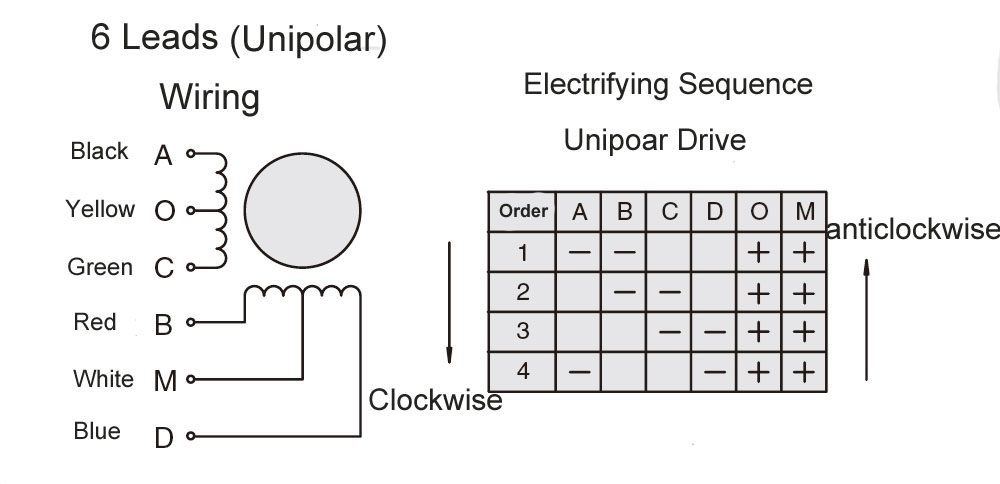
A unipolar drive circuit uses four transistors to control the two phases of a stepper motor. The stator winding structure of the motor consists of two sets of coils with a center tap, as shown in Figure 1. The entire motor has six wires connected to the outside world. The AC side cannot be energized at the same time (the same is true for the BD side ), otherwise the magnetic flux generated by the two coils at the magnetic pole will cancel each other out, resulting in only the copper loss of the coil. Since it actually has only two phases (the AC winding is single-phase and the BD winding is single-phase), the correct designation should be a two-phase six-wire stepper motor.
The driving circuit for a bipolar stepper motor is shown in Figure 2, which uses eight transistors to drive two sets of phases. The stator magnetic poles are wound with a single coil, and the direction of the magnetic pole is switched by changing the current direction of coils AC and BD. In the early development of stepper motors, unipolar motors gained some range of application due to the cost of semiconductor components, as they require fewer transistors in the control circuit. However, with the rapid development of semiconductor materials in the 1950s and 1960s, the cost of transistors greatly reduced, and bipolar motors saw a sharp increase in usage due to their performance advantages.
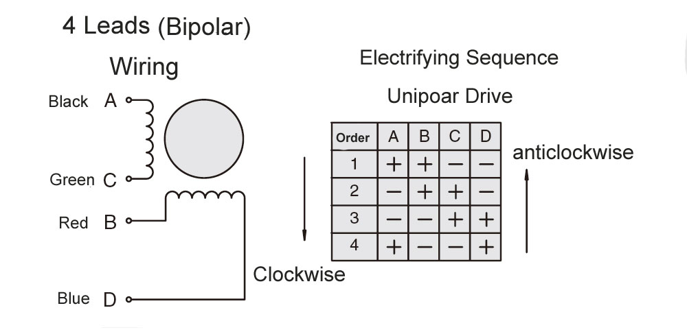
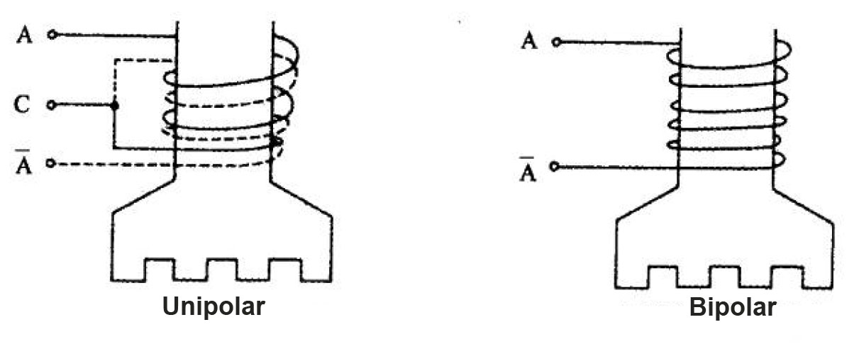
Figure 3 shows two winding methods of unipolar and bipolar. When the wire diameter is the same, the number of turns of the coil winding in the unipolar method is N, the resistance is R, and the number of turns of the coil winding in the bipolar method is 2N. , the coil resistance is 2R.
The following table compares the efficiency of unipolar and bipolar drive in a constant voltage drive circuit at low speeds. The product of current and coil turns is called ampere-turns, which is proportional to torque. If the two have the same speed, the output power is proportional to ampere-turns. Similarly, the bipolar current is V/2R, and the number of turns is also 2N, and the product is the same as that of unipolar, which is VN/R. In the case of input constant voltage drive, the comparison between unipolar and bipolar is shown in the table below. The current is only half of unipolar, and the efficiency at low speeds is twice that of unipolar.
Therefore, when there is a demand for high torque in small or low-speed applications, a bipolar motor and driver should be used. In high-speed applications, the number of turns of the bipolar motor increases, the inductance becomes larger, and the back EMF increases, which reduces the current and thus reduces the torque. Therefore, attention should be paid to comparing the torque with that of a unipolar motor.
| Unipolar | Bipolar | |
| Ampere Tturns | U1=V*N/R | U2=V*2N/2R=V*N/R |
| Input Power | W1=V²/R | W2=(V/2R)²*2R=V²/2R |
| Efficiency | η=U1/W1=N/V | η=U2/W2=2N/V |
Note: V is the applied voltage; R is the resistance of the motor coil; N is the number of unipolar turns
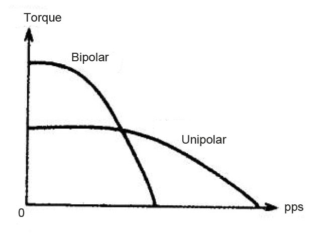
Figure 4 shows the characteristic curves of the unipolar stepper motor and the bipolar stepper motor, both of which adopt the same constant current drive mode. Generally, low-speed and high-torque load applications use bipolar drives, while high-speed drive applications use unipolar drives.